 MATHIASEN
MACHINERY, INC.
MATHIASEN
MACHINERY, INC.
Ref. # 14-141BENDING ROBOT OSCAM SMART FUTURA
MOBILE BENDING ROBOT 1 (M1)
The System is composed of:
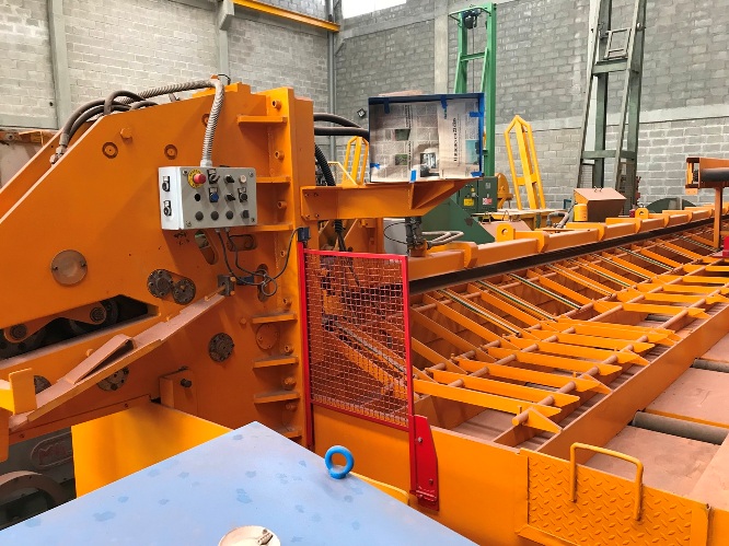
ONE BENCH MOD. BAS - HYDRAULIC
The bench is constituted by a series of motorized rollers, 130 mm in diameter, which rotate on ball bearings with hermetic closure, secured by supports fixed to the structure.
The rotation of the rollers is obtained by precision chains, which drive a self-braking electric gear motor.
Next to each roller is a lever for lifting the bars, which are hydraulically operated.
The levers are linked by a torsion arm, which synchronizes the movements. Thanks to this device, it is possible to lift the bars and advance them on the bending units, to facilitate loading.
On the front side there are two sliding shelves, to hold the bars when long bends must be made.
The electrical equipment is housed in a waterproof compartment.
M1 BENDING ROBOT OPERATING SYSTEM
The operating system of the Bending Robot includes:
• Race plane with rails and double-link precision drag chains
• central hydraulic clamp for locking the bars, equipped with hydraulic arm to unload the bends
• oleo dynamic switchboard with filter and heat exchanger, for oil cooling
• self-braking electric gear motors for the movement of bending units, with continuous speed control by means of a frequency inverter,
• encoder to control the position of the bending units,
• two mobile bending units, which move along the roller track, stopping with absolute precision at the programmed dimensions.
The units are equipped with hydraulic arm to unload the bends. A positioning arm is installed in a unit, which is automatically lifted before starting the work cycle, allowing to position the tip of the bars at the level planned for bending, without having to carry out measurement controls.
Both units can work independently, using the EASY ANGLE ELECTRONIC PROGRAMMER, for quick management of simple cycles.
The units are equipped with a series of bolts and rollers, which allow bending with the radius of curvature provided by the standard regulations.
* The stock unit of the bends is composed of 3 adjustable supports, which can be placed, sliding them on rails, throughout the whole system, according to the length of the finished bends. The supports directly collect the bends unloaded by the bending units by means of ejection arms, hydraulic control.
The machine is controlled by a system composed of industrial PCs and PLCs with which the work cycles are inserted and stored by means of the operator or by the remote PC.
The connection with the remote PC is made with an Ethernet or Wireless network connection.(optional)
The console (protection degree IP55) is mounted with:
• 15 ’touch screen color monitor, which displays all messages and graphic figures of the bends
• keypad with manual controls
• USB connection
• connector for barcode reader
The industrial PLC manages all the controls. The multilingual program installed manages:
• tracing data as provided by the current Standards
• Ethernet and USB connections
MOBILE FOLDING ROBOT 2 (M2)
Maximum bending length 12 m
The system is composed for the following elements:
ROLLER BENCH
The bench is made up of a track with 130 mm diameter motorized rollers covered in sound-absorbing and wear-resistant neoprene that hold some supports fixed to the structure and that carry ball bearings with hermetic closing and self-lubricating.
The rotation of the rollers is obtained by precision chains driven by a self-braking electric motor reducer with oil bath gears.
The track is made of carpentry in thick metal panels.
On the front of the roller track, two mobile arms support the long measurement bars during the bending phases.
M2 BENDING ROBOTS OPERATING SYSTEM
The M2 Bending Robot operating system includes:
• Race plane with rails and double-link precision drag chains
• Movable support arms to support long-sized bars that automatically position themselves between bending units at an equivalent distance
• Moving bending unit that moves along the roller track to position as programmed with extreme precision. The movement is activated by means of a self-braking electric gear motor at constant speed controlled by inverter.
• Fixed bending unit equipped with a pneumatic positioning stop that automatically rises at the beginning of the bending cycle to allow the alignment of bars to the correct zero point without requiring further measurement controls.
The two benders are equipped with all the bolts and rollers necessary to perform double work in compliance with the standard regulations.
• Pneumatic lifting arms with automatic movement for the transfer of the bars between the bending bolts and simultaneous execution of the finished material in the preceding cycle
• Stock system consists of 3 adjustable supports (on rails) according to the measure of the finished pieces where they are unloaded directly from the bending area.
The System is powered by a dedicated industrial PC and PLC. Production data can be inserted and stored directly for the operator or on a remote PC and compatible barcode reader.
The remote PC connection can be via Ethernet or Wireless (optional).
The control console (degree of protection IP55) is equipped with:
• 15” color touch screen
• Push button panel with manual controls
• USB connection
• Connection for barcode reader
The industrial PLC manages and controls all controls. The installed multi-language program controls:
• Tracing data as provided by the current Standards
• Ethernet and USB connections
• Data of the production carried out subdivided by list of work, client, works, weight, and diameter
• Diagnostic system of anomalies and errors that are displayed on the screen
• Signaling of scheduled maintenance operations that are displayed on the screen
• Upon request the program can be adapted for the receipt / transmission of data to the main production / optimization software.
SPECIFICATIONS
BASIC BENCH
Length 14,000 mm X Width 850 mm X Distance between rolls 1,000 mm MOVING BENCH
Max distance between bend axis: 12,000 mm
Min distance between bend axis: 1,100 mm
Electric motors for translation of the bending unit: 1.1 Kw each
CONTROL CONSOLE
Industrial PC with Pentium microprocessor
14 inch color monitor
BENDING UNIT
Bending capacity up to 36 mm diameter
2.6 kW motor
Two bending speeds:
slow: 3 seconds for a 180º angle
fast: 2 seconds for a 180º angle
AUTOMATIC SHEAR LINE HSEL MODEL 100 TON 3-WAY USEFUL LENGTH 12 M.
Its main structure consists of two beams, fixed to the two translation heads.
The structure, which supports the measuring canal, consists of a series of fixed brackets to one of the above-mentioned beams.
The three rails (see technical characteristics) are equipped with motorized rollers (see technical characteristics) and equipped with anti-noise plates.
The movement of the rollers is obtained by first quality chains.
Gear motors, with gears in oil bath, supply the movement.
The transfer of the bars from the measuring canal to the storage rails is carried out by fall. The drag of the bars is executed by means of an electric motor sent by the inverter. Every bar drag rollers, located before and after the blade, are mechanically connected to give the same drag speed to the bars in all conditions.
The choice between the first and second rail or the third rail is obtained by means of hydraulic drive arms that can be sent both automatically and manually.
The cutting is done with a hydraulic shear whose cutting capacity is written in the table.
The cart is self-sufficient in the transverse translation on rails thanks to two self-synchronized geared motors.
At the service of each control, high-end contactors are used and each motor is protected by magneto thermal relays.
The machine is controlled by a system made up of industrial PCs and PLCs through which the duty cycles can be adjusted and memorized by the operator or by the remote PC. The connection with remote PC is made with Ethernet or Wireless network connection (optional).
On a suspended console are mounted:
- 15 '' touch screen color monitor
- Keypad with manual controls
- USB connection
- Connector for optical barcode reader
The electrical and electronic system is mounted in a single cabinet (degree of protection IP55).
The industrial PLC manages all controls.
The multilingual installed program manages:
- Traceability data as prescribed by the new standards
- Ethernet, USB links
- Production data divided by work lists, customers, weight and diameter
- diagnose faults and anomalies by displaying them on the monitor
- Notice of scheduled maintenance operations by displaying them on the monitor
The program is predisposed to be connected (to receive and transmit data) to the main production / optimization management software.
SHEAR LINE
ø wire N. of wires cut simultaneously (850 N/mm2)
42 mm wire diameter 1 wire
32 mm wire diameter 2 wires
26 mm wire diameter 3 wires
20 mm wire diameter 4 wires
16 mm wire diameter 5 wires
12 mm wire diameter 6 wires
8 mm wire diameter 9 wires
Cutting power: 100 Ton
Feed speed of bars: Up to 110 m/min Moving speed pickup rails: 45m/min
Lateral translation speed:
16 m/min Roll diameter: 102mm Average power absorbed: 8.5 kw Maximum power during the work phase: 15Kw Total length: 13.55 m Total width: 2.40 m Total height with PC installed:
2.660 m Height of the mouth of introduction bars: 1.38 m Length of pickup rails:
12.20 m Width of pickup rails: 0.4 m length of bars cut (from - to):
0.20-12 m (removing the end cap from the measuring channel it is possible to run longer cuts) Scrap box length: 4m N. of scrap box compartments: 5
Capacity per-rail: 3500 Kg. approx.
Number of Rolls for each rail: 13
Weight: 10.500 Kg. approx.
Year of Manufacture: 2003